Daakshya Projects
Let’s Talk!
API Plant Design

API plants engineered from concept to commissioning.

One harmonised design framework for Active Pharmaceutical Ingredient facilities — built on cGMP, Good Engineering Practices and EHS, and flexible enough to run low, medium and high volume products on the same block.

10
Design disciplines resolved together
SF1–SF4
Single fluid temperature variants
ISO 8
Clean room powder processing
G+3
RCC block with gravity flow
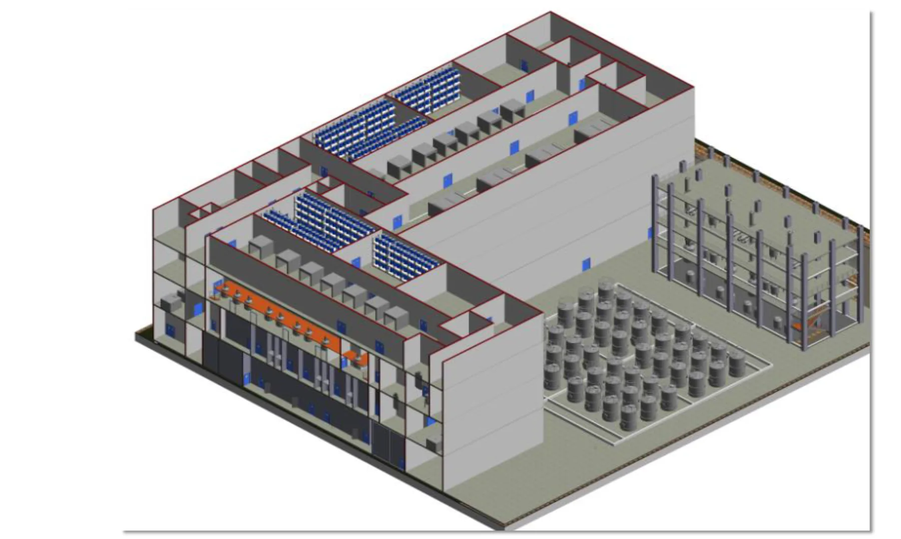
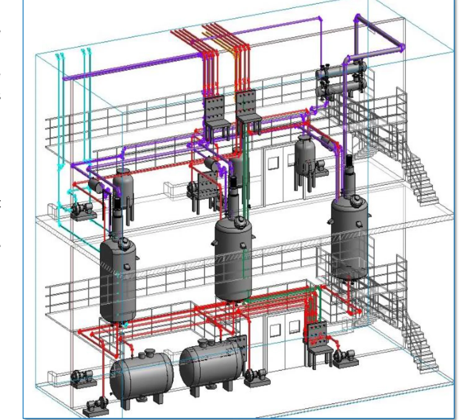
Isometric 3D view of an API manufacturing block
Design Intent

One design, resolved as one plant.

Process, utilities, HVAC, water, finishes, safety and warehouse are designed together rather than as separate packages, so the block behaves as a single validated facility from the first sketch to handover.

The design basis

  • Harmonised design approach across all Chemical Technical Operations (CTO) units
  • Current Good Manufacturing Practices (cGMP)
  • Good Engineering Practices (GEP)
  • Environment, Health and Safety (EHS)
  • Manufacturing flexibility with data integrity
  • Low, medium and high volume products, including intermediates and API
  • A single document that guides the facility from concept to commissioning
  • Standardised equipment sizing across blocks and trains

Key design focus areas

Compliance

  • cGMP and quality by design
  • DCS-operated plant with data acquisition
  • Access control for critical process areas

Containment

  • Closed building with once-through ventilation
  • Closed handling of solids and liquids
  • No cross contamination between products

Safety

  • Fire detection and protection
  • Emergency vent system
  • Efficient effluent handling

Ergonomics

  • Material handling designed to avoid hazards rather than control them
  • Mechanised handling with automation
  • Clean in Place (CIP) for fixed equipment

Future-ready

  • Flexible design for current and future products
  • Minimum design changes for product changeover
  • Standardised equipment sizing

Process flow

  • Fully integrated vertical process train
  • Large transfer station with full connectivity between all process equipment
  • Maximum gravity transfer
Design Scope

Ten disciplines, one mandate.

The concept covers the complete plant — every discipline below is engineered in house, with the interfaces resolved on paper before anything reaches site.

API Process

From unit process to powder in the drum.

A chemical reaction changes the molecule; the operations around it change only its form. The concept sequences both, so every charge, transfer and isolation happens in a controlled, contained step.

Unit process

The chemical reaction, where a chemical change takes place, is the unit process. It is classified as either a batch process or a continuous process.

Unit operation

The physical steps around the reaction are unit operations — separation, crystallisation, distillation, evaporation, extraction, filtration, drying and particle size reduction.
Batch process — the manufacturing sequence

  1. 01

    Material charging

    • Cleaning through a central CIP station or a local CIP skid
    • Solvent charging automated through the DCS with mass flow meters
    • Liquid charging depends on the nature of the liquid — hazardous liquids are charged through a dedicated charging station
    • Solids charged as jumbo bags, IBCs or through a PTS system
  2. 02

    Reaction

    • Heating and cooling through a single fluid system
    • Ramp-up and ramp-down controlled by the DCS with online sampling
    • Every reactor has a primary and a secondary condenser with a distillate receiver
  3. 03

    Work-up

    • A reactor with a conical bottom is used for work-up, fed from the feed vessel
    • Organic and aqueous layers are separated into a separation vessel below the work-up reactor
    • The spent layer is transferred to a high-COD collection pit
    • Layers are transferred to another reactor through the transfer panel
  4. 04

    Dissolution & crystallisation

    • Solvent, solids and charcoal are charged into the reactor through the PTS
    • Carbon and material are filtered through a candle filter or a charcoal pad
    • Sampling is collected through a closed sampling system after a clarity check
    • Intermediate, seed and solvent are charged under closed conditions
  5. 05

    Filtration & drying

    • Filtration and drying follow precipitation or crystallisation
    • Centrifuge and ANF, followed by the dryer: ANFD, RCVD, RVPD, ATFD, spray dryer, FBD or paddle dryer
    • Nitrogen or vacuum is the medium for filtration and drying
  6. 06

    Powder processing

    • Milling, sifting, micronising, blending and automatic weighing and packing
    • Quadro (co-mill), multi mill and micronizer achieve the required particle size
    • Transfer by PTS, pneumatic conveying or IBCs
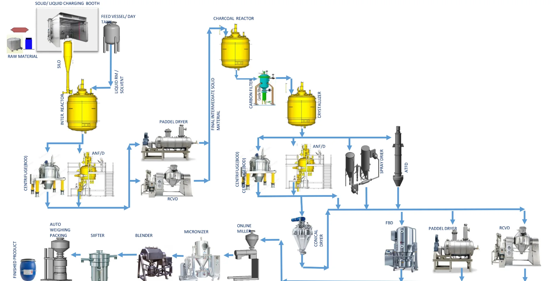
Typical API manufacturing process flow diagram from raw material charging to finished product packing
Typical API manufacturing process flow — charging, reaction, work-up, filtration, drying and powder processing.

Moving to continuous

How it is done

  • Batch size optimisation
  • Merging and elimination of intermediate steps
  • Solvent change or solvent optimisation
  • Change of equipment
  • Introduction of novel technology
  • Greater use of automation and mechanisation for material handling

Why it matters

  • Continuous processes are intrinsically safer in operation
  • Lower hold-up volumes in the reactor
  • Improved heat transfer from a higher surface area to volume ratio
  • Better control of exothermicity and less risk of a runaway reaction
  • Fewer batch failures and less variation — consistent product
  • Higher production yield and lower cost of manufacture
Plant Design & Layout

One block, four floors, gravity on our side.

The block is designed as a fully integrated vertical process train: materials enter at the top, move down through reaction, work-up and isolation, and leave as packed product.

Layout basis — a block strategy for every volume

ContentFiling Block small volume productsRepeater Block medium volume productsCommercial Block high volume products
Solution preparation reactor (L)1001,0004,000
Reaction reactor (L)250
500
2,000
3,000
5,000
6,000
8,000
Work-up reactor (L)630
1,000
4,0008,000
10,000
Total reactors (nos)16 + 2 nos8 + 1 no16 + 2 nos
Intermediate modules / train (nos)2 modules with 8 reactors each1 module with 8 reactors2 modules with 8 reactors each
Clean room modules (nos)2 modules (2 crystallizers)1 module (1 crystallizer)3 modules (3 crystallizers)
Special equipmentSpray dryer, ATFD, LLE, FFE, conical dryer, paddle dryer, Quadra mill

Building features

  • Ground + 3 floor RCC construction
  • Standardised floor heights: GF 0 m, FF 7 m, SF 13.5 m, TF 20 m
  • Multi-product design with no scope for cross contamination
  • Enclosed filtration, drying and powder processing for the intermediate area
  • Fully integrated vertical process train
  • Flexible design for current and future products
  • Maximum gravity flow
  • Horizontally separated wet, dry and milling operations
  • Minimal design updates required to produce a new product
  • Large transfer station with full connectivity between all reactors
  • Complete segregation of wet and isolation/drying areas
  • Proper segregation of process and technical areas
  • Dedicated solvent recovery plant with fractionation and flash recovery system, with tank farm
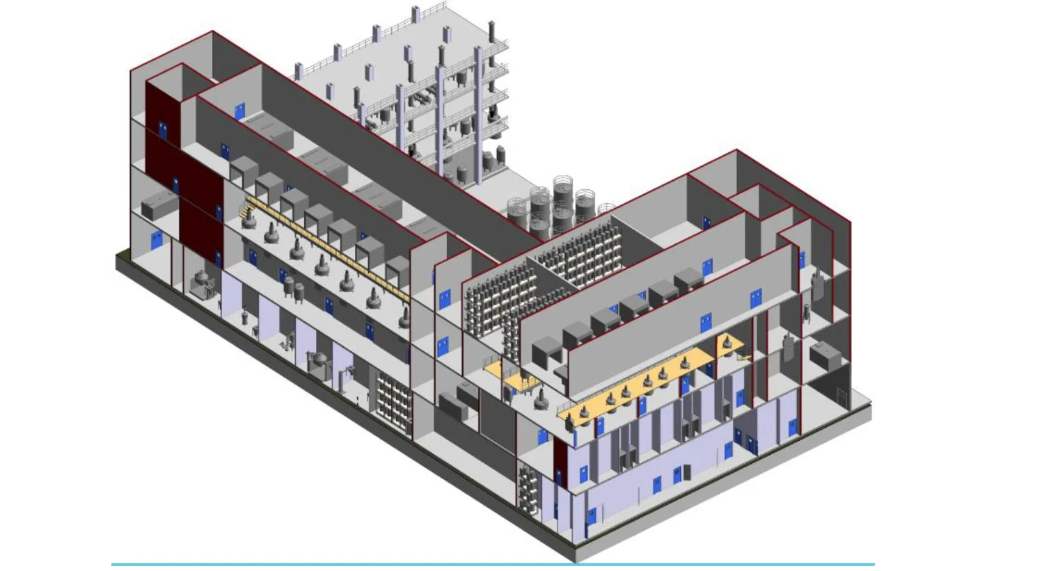
Isometric 3D view of the API block showing the vertical process train
Plant 3D view — the vertical process train inside the block.
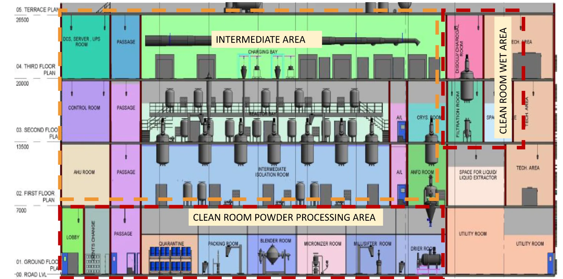
Sectional plant layout showing the intermediate area and clean room powder processing area
Sectional layout — intermediate area above, clean room powder processing below.
Process Equipment

Equipment specified to a standard, not to a supplier.

Reactors, filters, dryers and powder handling equipment are standardised in size and trim so that any train can run any product without re-engineering the block.

Equipment selected by process requirement

  • Crystallizer in SS316L / Hastelloy C with electro-polished internal finish
  • GLR lining with pharma glass and calibration mark
  • Agitated nutsche filter dryer (ANFD) preferred in place of a centrifuge
  • Bottom discharge or top discharge centrifuges
  • Paddle dryer preferred in place of a rotocone vacuum dryer (RCVD)
  • Fluidised bed dryer (FBD) with 12 bar design pressure
  • Spray dryer, closed loop with solvent recovery
  • Conical dryer / Nauta dryer
  • Agitated thin film dryer (ATFD)
  • Tray dryer / vacuum tray drier
  • Liquid-liquid extractor (LLE)
  • Falling film evaporator (FFE)
  • Online milling and sifter with Quadro / Fitz mill
  • Automated packing machine

Evaporator selection by product characteristics

Type of evaporatorCleanHigh volumeSolids or crystalsFoulingFoamyTemperature sensitiveViscous
Batch✓–––––✓
Horizontal tube✓––––––
Vertical short tube✓––––––
Vertical long tube✓✓–––––
Rising falling film✓✓–✓–––
Falling film✓✓✓✓–✓–
Forced circulation✓✓✓✓–✓–
Agitated thin film✓✓✓✓–✓✓

Evaporator selection matrix — a filled cell marks a duty the type handles well.

Reactor construction

  • Torispherical dished end type reactors
  • Cryolock agitator design for quick change
  • Two CIP nozzles located directly opposite each other
  • Dual insulation, pre-cladded with SS304
  • Double dry seal with Kalrez O-ring and debris collector
  • Dedicated primary and secondary overhead condensers with distillate receiver
  • Nitrogen blanketing and inertisation
  • Load cells for charge weighing
  • Online sampling system

Reactor standard sizing

Sr.SSR / Hastelloy (L)GLR (L)Vapour column (NB)Jacket utility nozzle (NB)Heat exchanger primaryHeat exchanger secondaryFeed vessel (L)25–30% of reactor volumeDistillate vessel (L)45–50% of reactor volume
110010080254.7 m²2.9 m²5050
22502508040100100
350063010040100250
41,0001,00010040250500
52,0001,600 / 2,000150507.0 m²4.7 m²5001,000
63,0003,000150501,0001,500
74,0004,0002005015.3 m²7.0 m²1,0002,000
85,0005,000200801,5002,000
96,0006,300250801,5003,000
108,0008,000250802,0004,000
1110,00010,00030010022.3 m²15.3 m²3,0005,000

Heat exchanger areas are shared across the reactor sizes they are bracketed with.

Filtration and drying detail

  • Eliminate wet cake handling wherever the process allows
  • Nitrogen or vacuum as the medium for filtration and drying
  • Mechanical seal with double dry seal, Kalrez O-ring and debris collector
  • Hot nitrogen for drying
  • Non-condensable process gases routed through scrubbers or the vacuum system
  • Dust containment, online sampling, CIP nozzle and solid discharge valve
  • Automatic bayonet lock arrangement
  • RCVD for faster drying at low drying temperature, with rotary joint, dust collector, lump breaker and IBC loading
  • RVPD — aggressive agitation and fast drying, with de-lumper and online sampling valve
  • Spray dryer — atomisation, drying and particle formation with internal finish not more than 0.6 Ra, nitrogen leak proof, closed or open cycle
  • FBD — supply air through 20 micron, 5 micron and HEPA 0.3 micron filtration, 12 bar design, humidification, CIP nozzles, dust explosion prevention and DP monitoring across filters

Piping philosophy

  • Intermediate area process piping in SS316 pre-fabricated with a matt finish
  • Acidic service: SS/PTFE inside the clean room, CS/PTFE in the intermediate area
  • Clean room piping from dissolution filtration outlet to crystallizer in SS316L, electro-polished and orbitally welded
  • Internal finish inside the clean room — SS316L at less than 0.6–0.8 Ra for equipment, piping and housing
  • Clean room internal piping support in SS304
  • Bolts and nuts in SS304, with a single bolt size per flange
  • Insulation cladding: powder coated in the intermediate area, SS304 in the clean room
  • Utility manifolds pre-insulated and pre-cladded — SS304 for clean room, powder coated for intermediate
  • Reactor utility manifold piping and fittings in CS seamless
  • Utility piping below 0 °C in CS seamless; above 0 °C in CS ERW, class C
  • Process piping in SS316 schedule 10 or as the process requires
  • Gaskets for process piping in PTFE envelope or complete food grade
Material Handling

Nothing handled in the open, nothing handled by hand.

Dispensing, charging and transfer are contained and, wherever the volume allows, mechanised — the transfer device is chosen by weight band and by the equipment being charged.

Packing received into the plant

Type of packingCapacity
Jumbo bag500 – 1,000 kg
HDPE / fibre drum25 – 100 kg
Paper / plastic bags25 – 100 kg
Carton box10 kg

Warehouse loading and unloading is handled with vacuum lifters and forklifts, with a de-dusting tunnel and palletiser on the dispatch side.

Dispensing

  • Solids are dispensed in a reverse laminar air flow (RLAF) booth with an integrated weighing balance, dispensing bench and drum lifter
  • A vacuum lifter handles material below 50 kg
  • Jumbo bags of 200 kg and above are handled through a jumbo bag unloading system

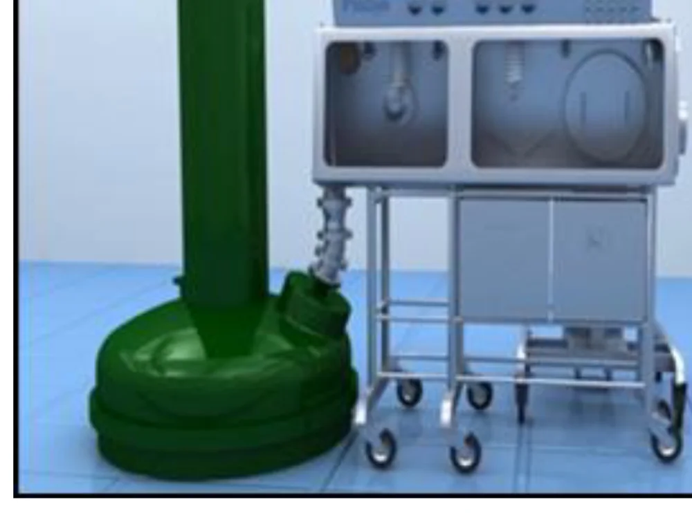
Glove box charging

  • Protects the product from exposure during seeding and the operator from potent material during operation
  • Creates a barrier between the operator and the exposed substance
  • Used for charging toxic, sticky or lumpy solids

PTS charging

  • Material of 50 kg and above is transferred through a PTS system
  • Mobile PTS serves multiple equipment
  • Mounted on the reactor top dish nozzle for charging
  • PTS with lump breakers for material that forms lumps
  • CIP provision on the PTS

Conveying

  • Vacuum and screw conveyors load and unload through drying and packing
  • Vacuum conveying above 200 kg
  • PTS above 100 kg
  • IBC and lifter between 50 and 100 kg
  • IBCs and silos for intermediate stages
  • Small quantities through a split butterfly valve with cleaning mechanism

Transfer device by weight band

Weight bandHopper with split butterfly valve(IBC + lifter) with split butterfly valveSiloPTSPneumatic conveyingJumbo bag dispensingDrum tilterScrew conveyer
Up to 25 kg✓–––––✓–
25 to 50 kg✓✓✓–––✓–
50 to 100 kg–✓✓✓––✓✓
100 to 200 kg––✓✓✓✓–✓
200 to 500 kg––✓✓✓✓–✓

Device selection is mapped equipment by equipment in the design basis — reactor, centrifuge, ANF/D, RCVD, conical dryer, paddle dryer, spray dryer, ATFD, FBD, milling, micronizer, blender, sifter and packing.
Solvent & liquid transfer

  • Mobile vessel, transfer panel, solvent charging manifold and ring main concept
  • Solvent transfer from the day tank to a mobile vessel by pump
  • Mobile vessel to process vessel under nitrogen pressure
  • Mobile tank vents connected to the scrubber header
  • Ring main concept where the requirement at the user point is less than 50 litres
  • Transfer panel with dedicated spool pieces for each solvent line and each reactor line
  • A special connector ensures only the selected solvent reaches the selected reactor at a time
  • Dedicated proximity switches on every spool piece, with quick release couplings
  • Inlet valves open automatically when the proximity switch confirms the HMI-selected combination
  • Spill collection chamber and drain valve, with blind flanges on unused spools
  • Lines maintained at slope to avoid hold-up

Hazardous liquid charging

  • Drums taken into a fume hood / drum booth for weighing and dispensing
  • Dedicated charging lines from the drum booth to the charging vessel, through flexible hoses
  • Vacuum drawn on the charging vessel to transfer the liquid from the drum
  • Weighing balance interlocked with the drum charging line on/off valve
  • Vacuum neutralised with nitrogen and monitored by a pressure transmitter
  • Transfer to the reactor through the charging vessel bottom valve
  • Control valve in the transfer line to regulate flow against time
  • Nitrogen blanketing of the charging vessel head space
  • Dip tube to prevent static build-up from free falling liquid
3D view of the solvent transfer panel, day tanks and reactors
Transfer panel — dedicated spools, proximity interlocks and spill collection.
Stainless steel charging glove box on a mobile trolley
Charging glove box for toxic, sticky or lumpy solids.
Automation

A recipe-driven plant with the records to prove it.

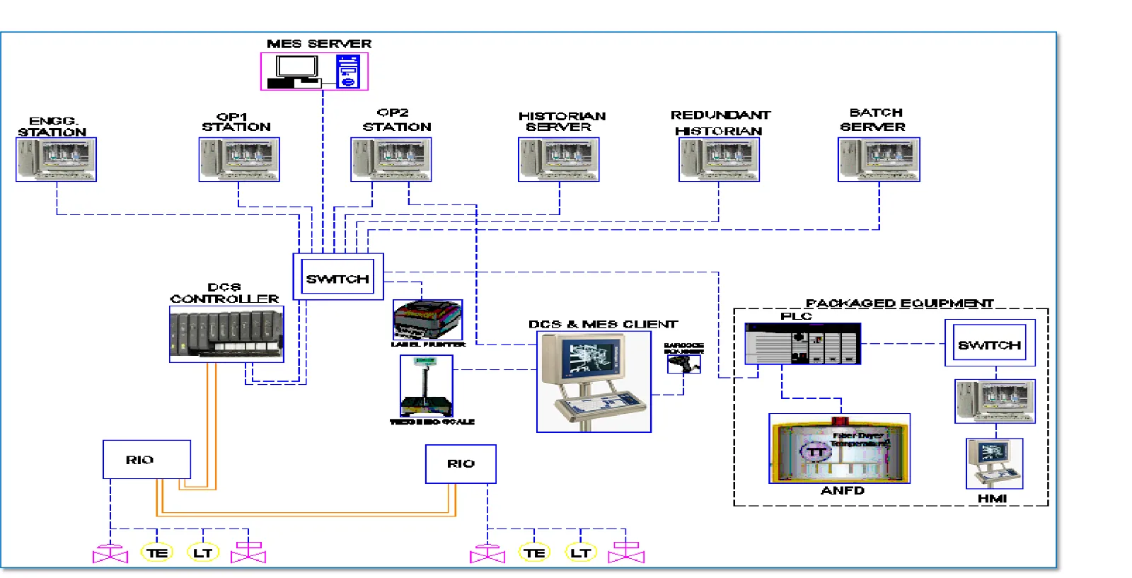
Plant operation is recipe driven through the DCS, with MES keeping track of manufacturing information in real time and generating the batch record as the batch runs.
Automation philosophy

  • Plant operation is recipe driven through the DCS
  • DCS capable of an MES interface; MES tracks all manufacturing information in real time
  • Automation covers utility control, solvent charging, chemical addition, layer separation, distillation, vent control, blanketing, filtration, drying, powder transfer, weighing and packing with online printing
  • The system generates the batch report as a Batch Production Record (BPR)
  • Adequate HMI on each floor, with dedicated HMIs for special equipment
  • Controllers, communication, power supply and data storage designed with redundancy
  • Weighing balances interfaced with printers for contemporaneous data printing, directly or through MES
  • System clock synchronised with a GPS clock
  • Field instruments flame proof / ATEX rated for Zone 1, gas group IIA and IIB
  • Day tanks with level transmitters and overflow protection
  • Gas detectors inside the block connected to the fire alarm system
  • Scrubbing, solution preparation, pH adjustment and VOC monitoring automated
  • Package equipment on PLC controllers, with data stored in the DCS historian
  • Control room located on the second floor for better monitoring and control
  • Separate trays for instrument and electrical cables — 300 mm apart up to 415 V AC, 1,000 mm for HT cables
DCS architecture with MES interface, MCC panels, UPS and AVR
DCS architecture with MES interface — field instruments, control layer and production reporting.

Controlled parameters across the plant

Reactors & vessels

  • Temperature and nitrogen pressure control
  • Vacuum, dispensing and feed control
  • Agitator RPM and level
  • Addition, pH and inertisation
  • Humidity, atmospheric distillation, venting

Solids equipment

  • Temperature and vacuum control on ANFD, RCVD, conical and paddle dryers
  • Spray dryer, ATFD, FBD, LLE and FFE instrumentation
  • Online milling, micronizer and blending sequences

Utilities & services

  • Utility control and solvent charging
  • Cleaning and CIP sequences
  • Weighing, packing and online printing
  • Data historian and batch reporting
Cleaning

Cleaning that is validated, logged and repeatable.

CIP is designed into the block rather than bolted on: every fixed vessel, filter, dryer and powder processing unit is covered by a repeatable, logged cycle.
CIP system

  • Provides effective, repeatable, reliable and validated cleaning cycles
  • Removes particles and bacteria from vessel and piping surfaces
  • Cleaning agent preparation, storage tank with agitator, alkali containers with dosing pump, supply and return pumps, heat exchanger, pipework and automation
  • Covers fixed vessels, reactors, filters, dryers, powder processing equipment and associated piping
  • Equipped with DCS and operator panel for machine settings
  • Logs process data and operator instructions
  • Retractable spray balls for process equipment

Typical CIP cycle

Pre-rinse

  • Water rinse of the vessel and line
  • Drain and verify

Caustic wash

  • Alkali wash at temperature
  • Air blow to clear the line

Acid wash

  • Post-wash rinse
  • Acid wash followed by air blow

Final rinse

  • Post-wash rinse
  • Final water rinse and air blow

Coverage

  • 360° hydro jet system
  • Retractable spray ball
  • Mobile CIP skid and central CIP skid

Documentation

  • Logged cycle data
  • Operator instructions
  • Cleaning matrix per equipment
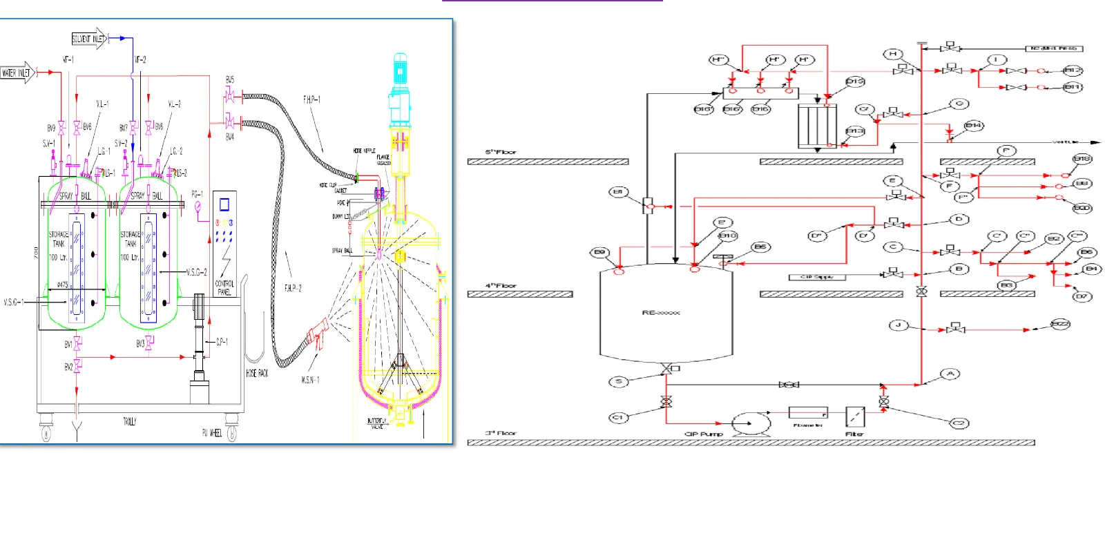
Typical reactor cleaning circuit with CIP skid, spray ball and return line
Typical reactor cleaning — CIP skid, spray ball and return line instrumentation.
Utility System

A single fluid system, four temperature variants.

One heat transfer fluid replaces steam and chilled water across the block. The system sits on the ground floor of the manufacturing block and is controlled through the DCS.

SF1

  • +130 °C
  • Reactor heating

SF2

  • +40 °C
  • Reactor and condenser

SF3

  • +8 °C
  • Condensers and receivers

SF4

  • −25 °C
  • Vent condensers and secondary condensers

Equipment utility matrix

Sr.EquipmentConnected utility
1ReactorSF1, SF2, SF3, SF4
2ANFDSF1, SF2, SF3
3RCVDDedicated heating / cooling TCU
4Primary condenserSF3, SF2
5Secondary condenserSF4
6Jacketed receiverSF3
7Vent condenser for tanksSF4
8Scrubber condenserSF3

Advantages

  • Precise temperature control
  • No hot and cold spots, giving consistent product yields and quality
  • More aesthetic piping network
  • No thermal shock to the reactor
  • No condensate loss
  • Rapid start-up and shutdown
  • Corrosion free, long life, non-pressurised
  • Energy consumption reduced 20–50% compared with steam
  • Very low maintenance cost
  • No water treatment and effluent treatment cost
  • No cross contamination of utilities
  • No freezing hazard

Considerations

  • Increase in operating expenditure
  • Single fluid with four temperature variants is considered for intermediate reactors
  • Single fluid with two temperature variants serves crystallizers and drying equipment
  • Cooling water, steam, air, nitrogen and breathing air are supplied from the central utility
  • The single fluid generation system is controlled through the DCS
Electrical

Power laid out for maintenance, not just for load.

MCC rooms, cable routing, earthing and lighting are planned with the process layout rather than after it.

Layout considerations

  • MCC room with positive pressure and air-lock entry
  • Cable entries sealed with fire retardant material
  • Continuous power supply for one in three lights, marked in the passage

General considerations

  • MCC as a TTP panel, double front type
  • Operating height minimum 300 mm, maximum 1,800 mm
  • Control cables (minimum) 1.5 mm² copper armoured; power cables (minimum) 2.5 / 4.0 / 6.0 mm² copper armoured
  • Minimum 4 core up to 16 mm²
  • Flame proof clean room areas (with false ceiling) use FLP LED fittings, bottom opening
  • Cable tray: perforated, powder coated
  • Switches and sockets wall flushed
  • Pharma section: prefabricated SS tray with CAP / pendant for cables
  • Adequate earth pits for static, motor and automation

Illumination levels

Process area

  • Not less than 300 lux

Office & control room

  • 400 – 500 lux

Service & warehouse area

  • 150 – 200 lux
HVAC System

Classified where it matters, ventilated where it does not.

Zoning, pressure cascades and filtration follow the process: ISO 8 clean room powder processing, controlled dry and wet areas, and ventilated intermediate areas.

Verified at design stage

  • Heat load calculation
  • Air changes per hour
  • Temperature and relative humidity requirement
  • Pressure zoning
  • Area classification — cleanliness class and AHU zoning
  • Air distribution scheme
  • Instrumentation system and control logic
  • Utility requirements

Room conditions — classified and ventilated areas

AreaRoomTemperatureRH
HVAC areaWet areasNMT 25 °CNMT 60%
HVAC areaDry areasNMT 25 °CNMT 60%
HVAC areaPowder processing areasNMT 25 °CNMT 60%
HVAC areaCommon areasNMT 25 °CNMT 60%
Ventilation areaIntermediate areaForced ventilationUncontrolled

Room conditions vary with the product requirement.

Cleanliness and air changes

Sr.ClassificationAHU filtration levelSupply terminal filtrationReturn terminal filtrationAir changes / hr
1ISO 8 (Grade D)G-4, F-7 & F-9HEPA (H-14) mounted in terminalReturn air riser with 10 micron filter (power process & drying area)NLT 20
2VentilationG-4, F-7Ceiling mounted diffuserCeiling mounted diffuserNLT 10–15

Pressure, air handling and dust

  • Differential pressure between classified and unclassified areas is a minimum of 15 Pa
  • Differential pressure between rooms of the same classification is 10–15 Pa
  • AHUs built from double skin panels with a thermal break profile and inner coving
  • Draw / blow through arrangement on re-circulatory mode to save refrigeration load
  • Once-through AHUs where the product or operation requires it
  • Mechanical ventilation of service and ventilated process areas through ventilation / exhaust units
  • AHUs take fresh air from the service floor, supplied by the ventilation unit and exhausted by inline exhaust fans
  • Dust extraction (DEX) wherever dust is generated
  • Hoods, pendants or hoses installed at the nearest source of dust generation
  • Interlock between the AHU and the dust extraction system
  • Spark proof blower and flame proof motor on dust extraction
  • Dust extraction hood mounted horizontally with a tri-clover clamp joint to prevent reverse flow on power failure
  • Evaporative cooling for human comfort in the process area
  • LEL / O2 sensors linked to the AHU to switch from recirculation to once-through
Water System

Two water systems, specified end to end.

Potable water and purified water are designed as separate systems with their own generation, storage and distribution, each with defined inlet and outlet specifications.

Potable water

  • Input and output specification defined for the site supply
  • Typical process flow diagram issued with the design basis
  • Feeds the purified water generation train

Purified water

  • Purified water management system with defined inlet parameters
  • Generation, storage and loop distribution
  • Typical PFD issued with the design basis
  • Designed to the project pharmaceutical water standard
Architectural Finishes

Surfaces that stay clean, and stay that way.

Finishes are selected for durability, cleanliness, functionality, maintainability and aesthetics — non-shredding, easily cleanable and resistant to fungus and bacteria.
Partitions & ceilings

  • Modular sandwiched clean room panels, powder coated and fire retardant
  • Mineral wool or rock wool infill
  • Panels sealed with food grade sealants
  • Washing areas in stainless steel
  • Partition thickness 50 / 100 mm with inbuilt return air risers
  • All corners with 50 / 70 mm radius powder coated 2D/3D covings and rounded corners
  • Walkable 50 mm ceiling, suspended from the RCC roof or self supporting
  • Supply and return air grilles, diffusers, risers and light fixtures powder coated
  • SS pendants through the ceiling for utility supply

Doors, view panels & flooring

  • Internal clean room doors flush type, in the same panel system, with view panels flush from both sides
  • Fire rated doors and emergency exits where statutory requirements apply
  • Powder coated fully flush double skin shutters with rockwool infill, two hours fire rating to IS 3614
  • Emergency doors with panic bars
  • Access control with emergency override on external doors to storage and process areas
  • Internal windows / view panels flush from both sides with double toughened glass, 50 / 100 / 230 mm sizes
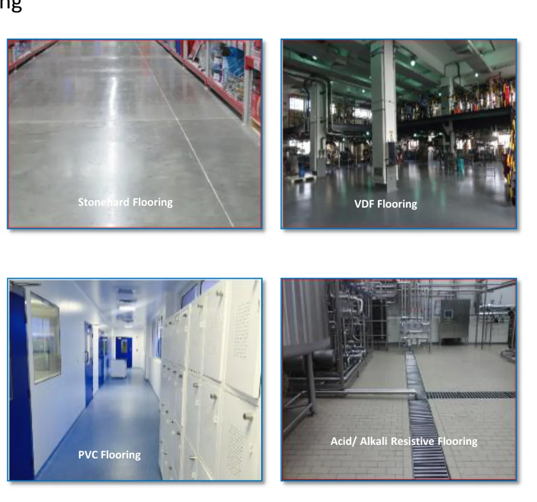
  • ISO 8 clean room flooring in epoxy / PU with 75 mm coving
  • Intermediate process areas, wash, technical area and corridors in granite or epoxy jointed flooring with 75 mm radius epoxy coving
  • Flooring selection driven by activity, chemical and mechanical resistance, cleaning requirement, aesthetics and maintenance
  • Furniture and finishes able to withstand trolley movement wear and tear
Flooring finishes used across the plant: stonehard, VDF, PVC and acid / alkali resistive flooring
Flooring palette — stonehard, VDF, PVC and acid / alkali resistive finishes used by area.

Staircase

Risers

  • Not more than 190 mm

Treads

  • Not less than 300 mm

Handrail & toe guard

  • Handrail 1,200 mm
  • Toe guard not less than 100 mm
  • Maximum 15 risers per flight
Safety & Environment

Safety designed in, not audited in later.

Fire protection, gas detection, emergency venting and earthing are integral to the block design, and the plant is planned to use less energy per kilogram of product.

Fire & life safety

  • Fire hydrant pipe ring around the block
  • Smoke and fire detection with manual call points in the intermediate and clean room areas
  • Sprinkler systems with water / foam in the intermediate area and tank farm
  • Emergency exit doors and speech panels
  • RD and SRV with an emergency venting system, and foam sprinkler protection for the tank farm
  • Zero access guards on all moving parts
  • Two hours fire rated walls between process and technical, MCC and utility areas
  • Fluorescent displays for fire and emergency exits, with escape route procedures displayed on every floor
  • Interlock between the fire alarm and door interlock systems, to disable door interlock during a fire
  • Door access control in the required areas

Process safety & environment

  • Nitrogen line with PRV and BPRV; breathing air point with PRV and end filter in each process area
  • Oxygen sensors with nitrogen valve cut-off
  • LEL sensors in closed process areas
  • Earth monitoring station with motor override interlock
  • Nitrogen blanketing / inertisation for reactors, storage tanks, filtration and drying equipment
  • Tank farm with separate spill / overflow collection pits and transfer pumps
  • Zone classification by safe / unsafe area marked in the layout
  • Wind stack provided
  • Double stage scrubbing system with auto pH adjustment, VOC monitoring and recording
  • Lightning arrester with counting facility; earthing pits for power in parallel, separate earthing for instruments
  • Dual earthing for all process equipment and vessels
  • Local exhaust ventilation above the charging nozzle as the process requires

Energy efficiency

  • Process and technical area segregation for an optimum ventilation design
  • Low temperature utility zone located in part of the building
  • IE3 motors and daylight, energy efficient lighting
  • Plug type fans in AHUs to save power and reduce maintenance and space
  • VFD on cooling tower fans, with CTI approved cooling towers for efficient chiller operation
  • Optimised duct and pipe routing to reduce transmission losses
  • EC fan, centrifugal chiller and screw chiller selection
  • Heat pump planned for monsoon reheating and winter heating
  • Modulating control valves in chilled and hot water lines to bypass during variable load
  • Maximum gravity transfer
  • MCC room within the building to minimise cable length and power loss
Warehouse Design

Storage that matches the process next door.

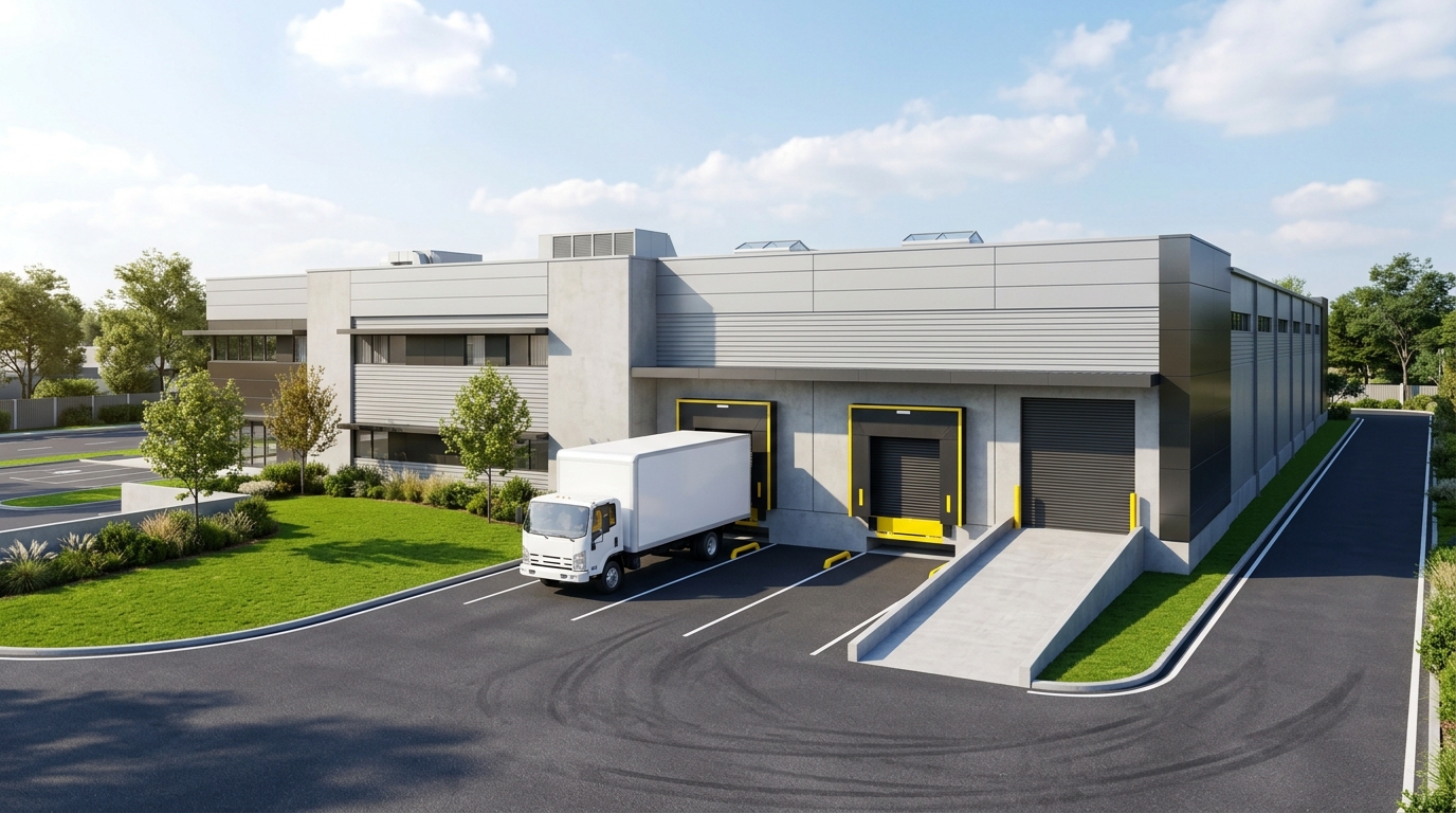
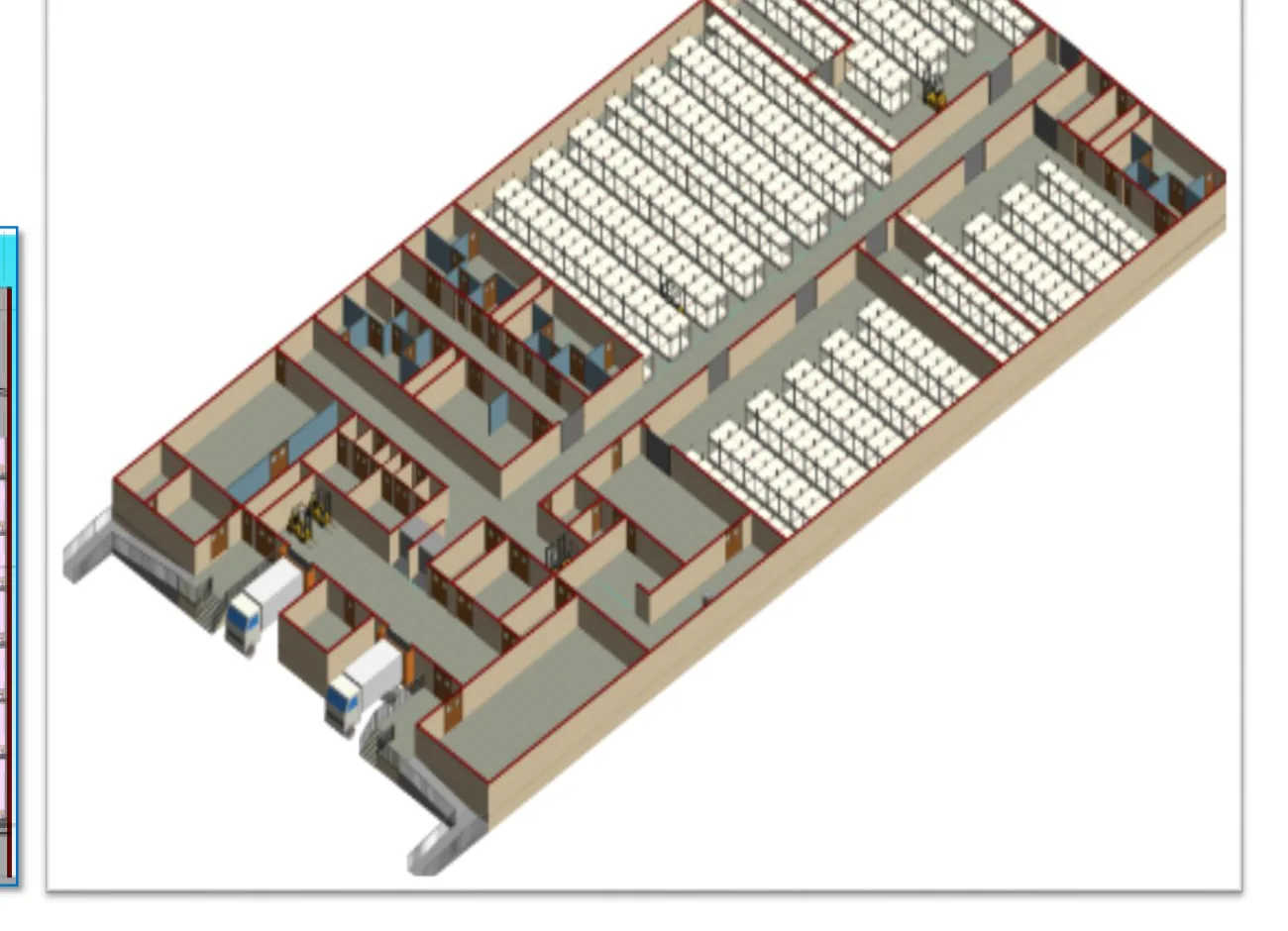
The warehouse is designed around raw material, intermediates, packing materials and finished goods, with powder processing inside the same envelope.
Design approach

  • Layout covers goods receiving, staging and de-dusting, change rooms and office, solid and liquid sampling, raw material storage at NMT 35 °C and NMT 25 °C, cold room storage at NMT 2–8 °C, packaging materials, quarantine, rejected goods, central dispensing, intermediates, finished products, dispatch bay and hazardous chemical storage
  • Very narrow aisle (VNA) racking in place of standard aisles to gain about 30% space
  • Inputs required: pallet information and type, receipt and dispatch vehicle information, site information, inventory information and degree of automation

Segregation to avoid mix-up

  • Solvents
  • Acids and alkalis
  • Flammable materials
  • Pressurised gases
  • Controlled drugs
  • Highly toxic substances
3D render of modern warehouse facility with loading bay
Warehouse block — receiving, storage, dispensing and dispatch under one roof.
3D view of the warehouse racking layout
Warehouse racking — VNA storage served by the main corridor.
Next step

Let’s design your API block.

Share your product basket, volumes and site, and we will come back with a block strategy, the unit operations it needs and an indicative footprint — the same thinking this concept is built on.

← Back to daakshya.samsidh.com